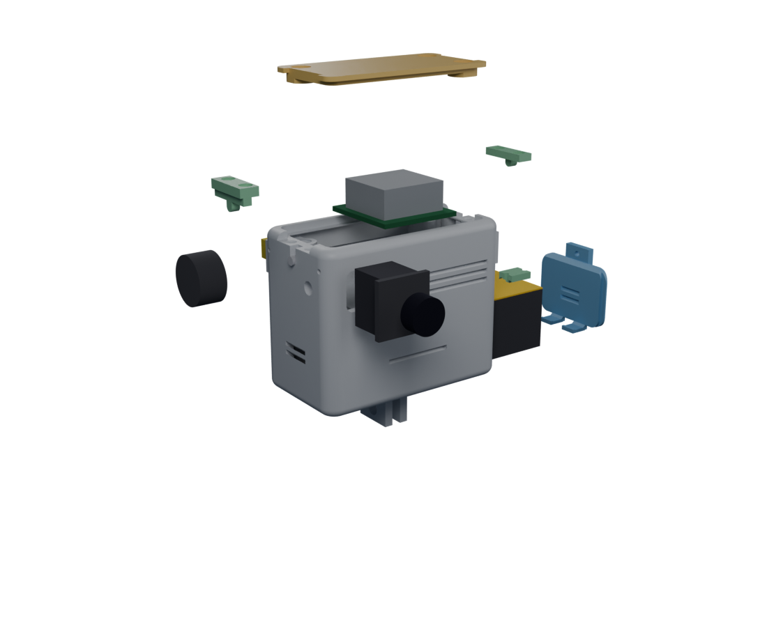
3D-Ansicht benötigt WebGL (Grafikbeschleunigung). Statische Ansicht — auf der Projektseite dreht sich das echte CAD-Modell.
3D-Ansicht benötigt WebGL (Grafikbeschleunigung). Statische Ansicht — auf der Projektseite dreht sich das echte CAD-Modell.
Every FPV builder expects a flight controller, a voltage regulator, a rat's nest of wiring. There is none of it here — a radio, a camera, a battery and an antenna, inside one printed body. The few connections that remain are minimal, and soldered once, properly, for flight. The restraint is the engineering.

A GoPro-form-factor transmitter that rides on the helmet. Drag to inspect it, or pull it apart to see what's inside.
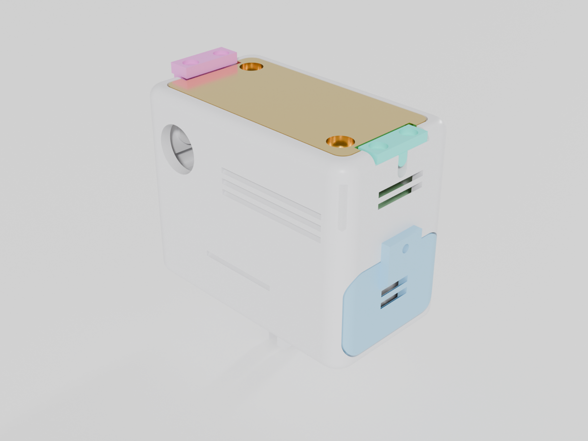
3D-Ansicht benötigt WebGL (Grafikbeschleunigung). Statische Ansicht — auf der Projektseite dreht sich das echte CAD-Modell.
drag to rotate · toggle assembled ↔ exploded · take-apart = scrub the explosion yourself
One exact figure each — the small, deliberate numbers a build quietly depends on. Sourced where sourced, modelled where marked, honest either way.
Everything above is the pitch. Everything below is the whole build — the chronological plan, the step-by-step assembly, the full bill of materials with dimensioned alternatives, the RF link-budget model, and the German-law reality. All install-free, all in the open.
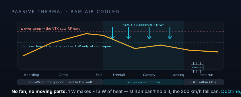
Chronological assembly with the three hardware-killer rules and the passive power/thermal doctrine — solder once, properly, for flight.
Assembly stepsEach step: the handgrip, the reason, and the failure picture — Sender 850 as a fixed, printed-in shelf.
Bill of materialsEvery part with a link, plus §6 — dimensioned alternative components (VTX, camera, battery, antenna, switch) so you can substitute honestly.
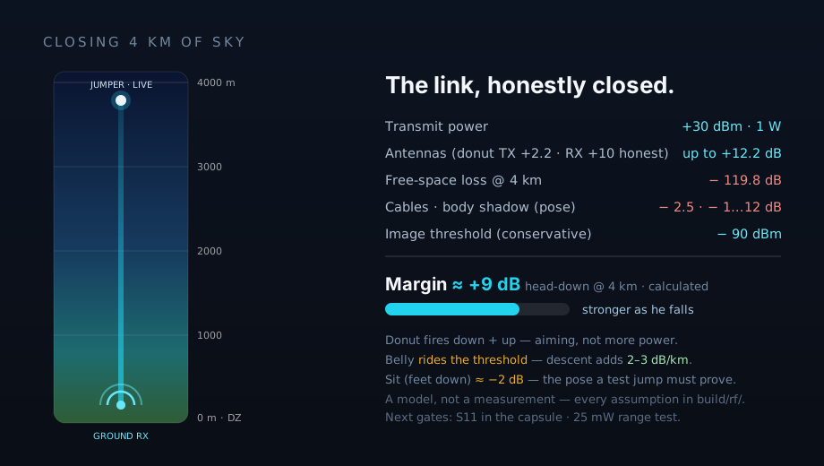
RFThe donut-omni link-budget model closing 4 km — a calculation, not a measured test, with every assumption on the table.
Legal · DEFrequency, power and the licensing reality for flying a 1 W 5.8 GHz link in Germany — read before you transmit.
CADThe build123d model that generates the case from a single spec file, with watertight and wall-thickness gates.
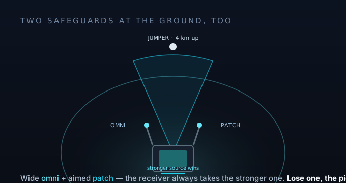
Radio doesn't go through a person well (−2…−12 dB by pose). Spin the jumper and watch each antenna's coverage move with the pose: the down patch — a legacy engineering study — aims a cone at the ground until the body swings it away; the donut omni fires down + up past the body. The omni is captive in the sender's wall, nothing to swap; on the ground, multiple fixed helix beams cover zenith and horizon, and the receiver fuses the branches.
The real CAD, live in your browser — assembled, exploded, and all three sizes (300: 59.5 × 39.5 × 48 · mid: 72 × 39 × 57 · 850: 71 × 40 × 56), with dimension tags on the geometry itself. Plus the antenna decks that argue the RF doctrine.
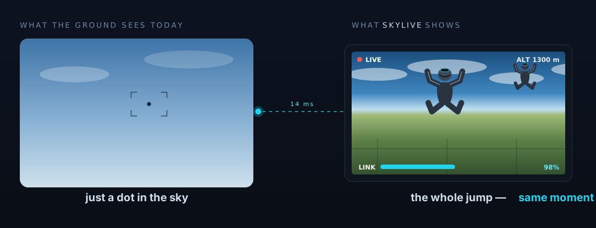
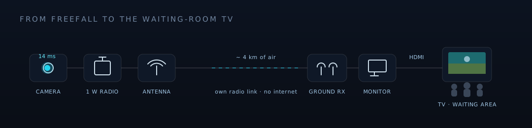
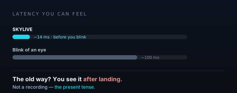
The supporting figures — from "a dot in the sky" to the full 4 km link budget and the passive-thermal doctrine.
The printed prototypes came back from a professional review with one recurring verdict: everything that broke, broke while removing support — always at a layer seam. The lesson is topology, not thickness: a feature must grow out of the printed body inside the layer plane, like the GoPro teeth do — not sit glued onto a seam. Since 07-26 every fix below is ported to all three sizes — one principle, three senders, each re-proven by its own gates. Try it yourself:
a geometry argument, drawn to the layer — not a strength simulation · the same principle moved the camera flange onto the shelf and put 45° fans under the door teeth
A 2 mm "optimisation" had silently eaten the power-switch bay: 11.8 mm left for a Ø12.5 body. Reverted — and the switch check is now a hard gate, probed against the whole body.
gate: 13.8 mm clear behind the VTX · envelope ∩ body = 0.026 mm³The clamp flange used to hang off a wall seam and tore off with the support. Now a foot welds it to the mid-storey shelf — with 45° fillets, in the layer plane.
point-cloud diff: change only in the target zone · 6/6 printabilityFree-standing fingers with "holes that were barely there" became one wall-to-wall clamp bridge — both cables in grooves, a solid latch bar screwed over them. One latch part fits both sides.
screw cores now fully jacketed · latch v3: 2× printed flatThe 90° hooks and blind floor channels are gone. Straight teeth sit in blind notches — and since the flap has a rounded corner right at the tooth root, 45° fans tie each tooth into the full plate.
door ∩ body = 0.000 mm³ · swing-in gates unchangedThe omni-cap side holders left without replacement — the rounded camera-side look wins. The roof lid dropped to two diagonal M3 screws; the freed corner belongs to the switch.
removal proven by diff — the old "gate" had probed inside the wallColour metadata in the STEP exports kept flipping lab printers into multi-material mode. All three models now export colour-free — slice the STLs, nothing else.
16× COLOUR stripped · rule: print from Druck/*.stl onlyAn omni antenna radiates a doughnut — and a doughnut has a hole. Point the antenna up (the default) and the hole points at the drop zone. SkyLive lays the antenna sideways: tilt it yourself, then hit spin — in freefall she turns constantly, and the signal toward the DZ must not care.
idealized omni doughnut (sin² gain) — the geometry argument, not a range promise · tilt 90° and spin: the DZ never leaves the maximum
The ground station listens through self-printed 5.8 GHz helix antennas — axial mode, RHCP: seven turns above a cup reflector lined with copper tape. Not a flat plate (the ground plane needs its 0.75 λ of copper and walls), and not the big cone either — the cone wins +4 dB at its peak and loses across the real elevation window. Minimax, again. Each helix rides a ball head, so elevation is set in the field, not baked into the print.
How many? One prototype first — bench blocks A/B and measurement D1 come before the second winding is ever wound. Then the receiver fuses four branches (one at the zenith, three fanned to the horizon, stock stubs off), and the self-built station scales the same pattern to seven. Honest gain: three estimators span 10.7–13.9 dBic — nothing here is measured yet, and the plan says so out loud.
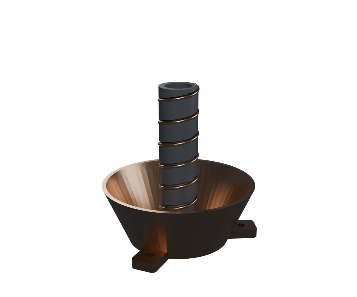
printed in ASA — a black PLA antenna sags on a summer drop zone (Tg 55 °C)